The preferred method to add your own components to ESPHome is to use External Components.
If you want to make all components available use this config.
external_components:
  - source:
      type: git
      url: https://github.com/mikelawrence/esphome-components
If you want to make specific components available use this config.
external_components:
  - source:
      type: git
      url: https://github.com/mikelawrence/esphome-components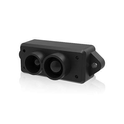
components: [ tfmini ]These ToF (time of flight) range finder sensors are compact, self-contained range finders. They support both UART and I2C communication but this component only supports UART communication.
This component supports the following Benewake LiDAR Range Finder Sensors.
| TFMini Plus | TFMini-S | TFLuna |
|---|---|---|
 |
 |
 |
# Sample configuration entry example
sensor:
  - platform: tfmini
    model: TFMINI_PLUS
    sample_rate: 10
    low_power: true
    version:
      id: tfmini_version
      name: "TFMini Firmware Version"
    signal_strength:
      id: tfmini_signal_strength
      name: "Signal"
    distance:
      id: tfmini_distance
      internal: true
      name: "TFMini Distance"
      accuracy_decimals: 1
    signal_strength:
      id: tfmini_signal_strength
      name: "TFMini Signal Strength"
      filters:
        - throttle: 1s
- model (Required, string): The model of the Range Finder Sensor. Options are
TFMINI_PLUS,TFMINI_SorTF_LUNA. - uart_id (Optional, string): Manually specify the ID of the UART Bus if you use multiple UART buses.
- sample_rate (Optional, integer): The frame rate at which the sensor will output sensor data in samples per sec. For the TFMINI_PLUS and TFMINI_S the range is 1-1000. For the TFLuna the range is 1-500. Note when low_power mode is set to true for the TFMINI_S and the TFLuna model the is significantly lower from 1-10. Default is 100.
- config_pin (Optional, Pin Schema): This pin when connected will be set high to enable UART mode. (TF_LUNA only)
- low_power (Optional, boolean): Turns on low power mode. This also requires sample_rate to be 10 or less. (TF_LUNA, TFMini-S only)
- distance (Optional): Distance in cm. For the TFMINI_PLUS and TFMINI_S the range is 10-1200cm. For the TFLuna the range is 20-800cm. A distance of 10000cm means the sensor is not receiving enough signal, most likely open air. A distance of 0cm means the sensor is saturated and there is no measurement possible. All Options from Sensor.
- signal_strength (Optional): Represents the signal strength with a range of 0-65535. The longer the measurement distance, the lower signal strength will be. The lower the reflectivity is, the lower the signal strength will be. When signal strength is less than 100 detection is unreliable and distance is set to 10000cm. When signal strength is 65535 detection is unreliable and distance is set to 0cm. All Options from Sensor.
- temperature (Optional): Internal temperature in °C. It's not clear how useful this sensor because it certainly does not measure room temperature. All Options from Sensor.
- version (Optional): Firmware version of Range Finder Sensor. All Options from Sensor.
The STUSB4500 is a USB power delivery controller that supports sink up to 100 W (20V, 5A). It has Non-Volatile Memory that can be programmed with your PDO profile so when you connect to a USB-C Power Source it will immediately negotiate your power delivery contract.
STUSB4500 board from SparkFun Electronics

There are 3 PDOs that you can configure with PD1 fixed at 5V. You can vary PD1's current. If you have all three PDOs configured the STUSB4500 will try to negotiate a contract with the PDOs in the following order: PD3, PD2 and PD1. If you don't want PDO1 negotiated then set power_only_above_5v: true.
The configuration below the STUSB4500 will try to negotiate 12V @ 3A then 9V @ 3A. If neither are available then it won't negotiate at all.
# Sample configuration entry example
sensor:
  - platform: stusb4500
    alert_pin: GPIO8
    snk_pdo_numb: 3
    v_snk_pdo2: 9.00V
    i_snk_pdo2: 3.00A
    v_snk_pdo3: 12.00V
    i_snk_pdo3: 3.00A
    power_only_above_5v: true
    usb_comms_capable: true
    pd_state:
      name: "PD State"
    pd_status:
name: "PD Status"- flash_nvm (Optional, boolean): When set to
truethe STUSB4500 NVM will be flashed with the current settings but only if different. To be on the safe side you should not leave this set totrue. A power cycle is required to renegotiate. Default isfalse. - default_nvm (Optional, boolean): When set to
truethe STUSB4500 NVM will be flashed with default settings but only if different. To be on the safe side you should not leave this set totrue. A power cycle is required to renegotiate. Default isfalse. - snk_pdo_numb (Optional, integer): Set the number of PDOs that should be negotiated. Range is 1 - 3. A value of 3 means PDO3, PDO2 and PDO1 can be negotiated. A value of 2 means PDO2 and PDO1 can be negotiated. A value of 1 means only PDO1 can be negotiated. Default is 3.
- v_snk_pdo2 (Optional, float): This is the desired PDO2 voltage. Range is 5.0 to 20.0. Default is 20.0.
- v_snk_pdo3 (Optional, float): This is the desired PDO3 voltage. Range is 5.0 to 20.0. Default is 15.0.
- i_snk_pdo1 (Optional, float): This is the desired PDO1 current. Range is 0.0 to 5.0. 5.0A is only available with 20V. For all other voltages the maximum current is 3.0A. Default is 1.5.
- i_snk_pdo2 (Optional, float): This is the desired PDO2 current. Range is 0.0 to 5.0. 5.0A is only available with 20V. For all other voltages the maximum current is 3.0A. Default is 1.5.
- i_snk_pdo3 (Optional, float): This is the desired PDO3 current. Range is 0.0 to 5.0. 5.0A is only available with 20V. For all other voltages the maximum current is 3.0A. Default is 1.0.
- shift_vbus_hl1 (Optional, percentage): This is the percentage above PDO1 voltage when the Over Voltage Lock Out occurs. Range is 1% to 15%. Default is 10%.
- shift_vbus_ll1 (Optional, percentage): This is the percentage below PDO1 voltage when the Under Voltage Lock Out occurs. Range is 1% to 15%. Default is 15%.
- shift_vbus_hl2 (Optional, percentage): This is the percentage above PDO2 voltage when the Over Voltage Lock Out occurs. Range is 1% to 15%. Default is 5%.
- shift_vbus_ll2 (Optional, percentage): This is the percentage below PDO2 voltage when the Under Voltage Lock Out occurs. Range is 1% to 15%. Default is 15%.
- shift_vbus_hl3 (Optional, percentage): This is the percentage above PDO3 voltage when the Over Voltage Lock Out occurs. Range is 1% to 15%. Default is 5%.
- shift_vbus_ll3 (Optional, percentage): This is the percentage below PDO3 voltage when the Under Voltage Lock Out occurs. Range is 1% to 15%. Default is 15%.
- vbus_disch_time_to_0v_ (Optional, time): Coefficient used to compute VBUS discharge time to 0V. Range is 84ms to 1260ms and must be a multiple of 84ms. Default is 756ms.
- vbus_disch_time_to_pdo_ (Optional, time): Coefficient used to compute VBUS discharge time when transitioning to lower PDO voltage. Range is 24ms to 360ms and must be a multiple of 24ms. Default is 288ms.
- vbus_disch_disable (Optional, boolean): When set to
truethe STUSB4500 NVM will stop discharging VBUS. Default isfalse. - usb_comms_capable (Optional, boolean): When set to
truethe STUSB4500 will tell the connected device that USB communications are possible. Default isfalse. - snk_uncons_power (Optional, boolean): When set to
truethe STUSB4500 will tell the connected device external power is available. Default isfalse. - req_src_current (Optional, boolean): When set to
truethe STUSB4500 will report the source current from source instead of the sink. Default isfalse. - power_ok_cfg (Optional, boolean): Selects the POWER_OK pins configuration. Options are
CONFIGURATION_1,CONFIGURATION_2orCONFIGURATION_3. Default isCONFIGURATION_2. - gpio_cfg (Optional, boolean): Selects the GPIO configuration. Options are
SW_CTRL_GPIO,ERROR_RECOVERY,DEBUGorSINK_POWER. Default isERROR_RECOVERY. - power_only_above_5v (Optional, boolean): When set to
truethe STUSB4500 will enable VBUS only if PDO2 or PDO3 was negotiated. WhenfalseVBUS is enabled at 5V when connected to a non-PD charger. The available current is unknown. Default isfalse.
- pd_state (Optional): Current PD State as an integer. Range 0 to 3 where 0 is no PD negotiated. A value of 1, 2 or 3 indicates which PDO was negotiated. All Options from Sensor.
- pd_status (Optional): Easy to read PD State (e.g. "12V @ 3A" ). All Options from Sensor.
When the GPIO is configured for software control gpio_cfg: SW_CTRL_GPIO these actions control the state of the output.
- stusb4500.turn_gpio_on Will pull the GPIO low.
- stusb4500.turn_gpio_off Will set the output to High-Z.
Example using automations...
on_value_range:
  - below: 5.0
    then:
      - stusb4500.turn_gpio_on: pd_controller
Example in lambdas...
- lambda: |-
  id(pd_controller).turn_gpio_on();
Caution
When configuring the STUSB4500 for the first time you should realize the default configuration will allow up to 20V on VBUS. Make sure your circuit can either support 20V or configure the NVM using a Power Source that will NOT produce 20V like USB 2.0 or a non-PD USB-C charger.
Using the STUSB4500 ESPHome component requires the following steps:
- Set the configuration variables to match your requirements. The sample configuration above sets PDO3 to 12V @ 3A, PDO2 to 9V @3A and PDO1 is disabled because
power_only_above_5v: true. This means it will first try to negotiate 12V @ 3A. If unavailable then it will try 9V @ 3A. If is unavailable no PD will be negotiated. Either thepd_stateorpd_statussensor will let you know if there is a problem. - Add
flash_nvm: trueto the configuration. You should see the following messages in your log.If you forgot to add[00:10:03][C][stusb4500:112]: STUSB4500: [00:10:03][E][stusb4500:119]: NVM has been flashed, power cycle the device to reload NVMflash_nvm: trueto the configuration you will see an error in the log.[00:06:27][C][stusb4500:112]: STUSB4500: [00:06:27][E][stusb4500:114]: NVM does not match current settings, you should set flash_nvm: true for one boot [00:06:27][C][stusb4500:130]: PDO3 negotiated 9.00V @ 3.00A, 27.00W - Power cycle your board. Make sure
NVM matches settingsis present in the log and that one of your PDOs was negotiated. Configuring the STUSB4500 can be a bit finicky, but keep at it.[00:00:19][C][stusb4500:112]: STUSB4500: [00:00:19][C][stusb4500:116]: NVM matches settings [00:00:19][C][stusb4500:130]: PDO3 negotiated 12.00V @ 3.00A, 36.00W - The STUSB4500 comonent does check to see that the NVM is indeed different before flashing the NVM but it is prudent to remove the
NVM matches settingsafter it is clear the STUSB4500 is worked as configured.