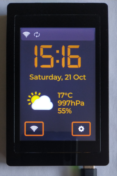
OTC or just Online Table Clock is, as it says, my concept of table clock that is able to get time/weather related data from the internet.
6.List of external tools/resources
OTC project is based on ESP32 Terminal module. The module is equipped with ESP32S3 MCU with 16MB Flash and 8MB RAM memory, 480x320 LCD screen with capacitive touch and USB-C port for serial programming. The firmware has been written in pure C, and is based on FreeRTOS port for Espressif microcontrolers. The main tools used for this project are:
To obtain weather and location data, is uses free Weather API, and cJSON library to parse the data. Encryption and decryption of stored wifi passwords are done with Espressif's port of Mbed-TLS library.
This project is for learning purposes only. Feel free to use it.
Current version - v1.1.0
In this version OTC is able to:
- search for available wifi access points and represent the results on the screen. Each one AP within the list shows SSID name, signal strength and informs that AP is protected or not.
- connect with chosen AP, show details about connected AP
- ask user to enter AP password, save encrypted password to internal file
- search, decrypt and use saved password to connect with AP
- delete saved password for chosen AP
- get current time, timezone and basic weather data for current location
- get detailed weather data for current location
- change and store color theme without reseting the device
- change and stotre backlight brightness from UI
- change, store, and play 4 different alarms with buzzer sound
The project is still under development. Next milestones are:
- add OTA firmware update
The features that might be add in future are:
- add RTC and low-power support
- add Li-Ion battery management
- add statistics screen
- add logfile
Although The ESP32 Terminal module is ready to use dev board, one modification has to be done. Pin 4 of touch controller (PENI) generates an interrupt when touch is pressed; because of insufficient number of pins, that pin is disconnected with R35 jumper from GPIO0, so GPIO0 is used only to enter BOOT mode with "BOOT" switch. Observations showed that both functions (entering boot mode and recieveing touch interrupts) can be covered by GPIO0 without any unexpected behavior, so R35 has been jointed.
Internal flash memory is configured as Quad-SPI, and works with 80MHz. Internal RAM memory is configured as Octal-SPI and works with 80MHz as well. The .bss and Wifi/LwIP resources can be placed into external RAM. Instruction cache is set to 32kB, data cache to 64kB. Internal Wifi task is pinned to core 1. The Timer task priority is set to 5.
The folowing tasks are created in this project:
-
app_main
The default task created by FreeRTOS. Here everything starts. It is used to initialize peripherals, cJSON library, and create all other tasks. The app_main task creates also synchronization point for the firmware - all the other tasks will be started in the same moment only if all initializations are done. If app_main reaches this point it deletes itself.
-
Wifi_Task
This task is used to perform any Wifi related operations like:
- initialize Wifi and NetIF resources
- start scan for available access points and report the results to UI
- perform connect and reconnect routine with obtained access point data
- manage WiFi events and report them to UI
-
SPIFFS_Task
This task is used to store any data for future use. It perform read/write operations within internal filesystem partition (SPIFFS) and internal Non-Volatile Storage partition (NVS).
The SPIFFS partition is used to store Wifi credentials encrypted with AES CBC method. For that, the SPIFFS_Task is able to do the following:
- mount a filesystem to a partition within internal memory
- create, restore, make backup and check correctness of wifi password files
- read AES 256-bit key stored in eFuse
- encrypt/decrypt received password with AES CBC method
- store encrypted password with all data needed do decrypt (as JSON object)
- delete the password and all related data if needed
The same partition is used to store all alarms data. For that, the task do the following:
- create, restore, make backup and check correctness of alarms files
- store all data in this file as JSON object, and load them to RAM
The NVS partition is used to store OTC config. For that, the SPIFFS_Task is able to do the following:
- create config structure in RAM and then copy stored values from NVS to the config
- read and set default values from FLASH if needed
- set new config value to NVS and then update it in RAM structure
In this version user can change the color theme and backlight value only, so just these two keys are stored within NVS. There will be much more stored settings in future.
-
OnlineRequests_Task
The task is used to perform any network request of data. It includes:
- get current time from SNTP server
- get timezone and current weather based on current IP address (HTTP)
- get detailed forecast weather for today based on current IP address (HTTP)
OnlineRequests_Task is also able to parse received data (as JSON) and report them to UI and Clock_Task if needed
-
Clock_Task
The task is used to perform any Clock-related operations like:
- update time displayed by UI every minute
- monitor clock synchronization status and report it to UI
- send synchronization requests
- check every minute if any alarm should be played
-
UI_Task
The task is used to create and manage every element within User Interface. This is the only one task that is allowed to use LVGL library API (except Display_Task that is responsible for redrawing the display content). Because of that, the UI_Task is able to do the following:
- read last used theme, initialize all styles within the app in according to the theme
- initialize all screens and all objects in according to the styles
- manage UI events and UI objects in runtime
- restyle all objects when style changes
-
Display_Task
The task is used to initialize LCD driver and perform any operation within the LCD. It also initializes the LVGL library, and integrates it with LCD driver and Touchpad driver. When LVGL is ready to use, the Display_Task calls only one function that is LVGL handler to perform redraw operation. Because the UI_Task simultaneously calls LVGL API, it was necessary to use Mutex protection before every call of any LVGL function. The LVGL_MutexHandle is shared between these two tasks to avoid data corruption.
-
TouchPad_Task
The task is used to initialize Touchpad driver and configure an interrupt routine if display is touched. When interrupt occurs, the TouchPad_Task reads the data from touchpad controller, and store it to the queue. The LVGL library can then read the last stored value.
-
SDCard_Task
The task is used to initialize SD Card peripherals and mount file system within the card. When it's done, the task deletes itself. The SD Card is used to store images for weather icons.
-
PWM_Task
The task is used to perform any operation related to Buzzer. It recieves requests to play simple sound, then executes the sequence stored in flash.
Clock set/synchronize
System clock may be in one of 3 states:
-
clock_not_set
If the system date is before 2020, it means that clock was not set properly. In this case, on the main screen, the time is represented by "--:--" value, and nothing else is displayed. The Clock_Task sends ONLINEREQ_TIME_UPDATE request every minute until the date is valid. -
clock_not_sync
If the system date is after 2020, it may be possible that clock was set properly, but synchronization is required. In this case, the Clock_Task sends requests to update time from SNTP service, and timezone from HTTP API. If both of them were synchronised, clock changes it's state to clock_sync -
clock_sync
The Clock_Task checks every minute if the time for synchornization has come (synchronization is performed once per hour). If yes, it sends synchroniztion requests, and changes the clock state to clock_not_sync.
To perform any action every minute, the Clock_Task calculates time in seconds to next full minute, and sets the timer to notify it exactly when the minute changes to the next.
The video below shows the situations: when OTC starts, the clock is not set. After connecting with access point "Test_AP", the clock is set by SNTP service, then finally synchronized with timezone received from HTTP.
Display current/forecast weather
The current weather data are displayed on the main screen, below current time and date. This area contains numeric values on the right side, like temperature, pressure and humidity, and big icon on the left side that represents current weather in general. Data are obtained from HTTP together with timezone, and are updated once every hour. Location is based on OTC IP - function provided by weatherapi.com API.
To see forecast weather data for today, user should click the weather icon on the main screen. The UI_Task receives an event, and sends ONLINEREQ_DETAILED_UPDATE request. The request is processed by OnlineRequests_Task - it receives JSON from HTTP, parse it, and reports event back to UI. Finally, UI_Task sets all values on the weather screen, and swipes it on top. Every time when use clicks the main screen weather icon, new HTTP request is sent, and weather data are updated.
The weather screen contains:
- current location, city and country name are displayed at the top left corner
- weather icon that represents the weather during the day in general. It is located at the top right corner
- average temperature located at the middle of the screen. It is composed of 270deg arc and the number inside it. The color of the arc is changed according to the temperature.
- min/max temperature located at the bottom of arc. It shows minimum and maximum temperature during the day
- four icons located in the bottom half of the screen. They shows the sunrise and sunset time, maximum and average wind speed, total precipitation and percentage chance of rain and snow
The video below shows the situation when user wants to see forecast weather for today.
Search and list for available Wifi networks
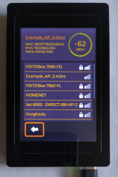
Regardless of wifi connection status, user is able to scan and display available wifi access points. To perform the scan, user should click the wifi button on the main screen. The UI_Task receives an event, deletes all elements within the list, then swipes the wifi screen on top, and sends "StartScan" request to the Wifi_Task. When scan is done, the Wifi_Task sends results back to UI_Task. Information provided as results contain:
- SSID of access point
- signal strength
- is AP protected or no
All found AP's are then listed on the wifi screen. The list is located below access point details. The list is scrollable when number of AP's exceeds the maximum number that fits to the screen. When AP name doesn't fit to the screen because it is too long, it will be scrolled horizontally from one side to the other.
The video below shows multiple user request to scan for available wifi network.
Connect to selected Wifi network
When one of available AP's has been clicked, the UI_Task sends get_pass_and_connect request to the SPIFFS_Task. The SPIFFS_Task checks if a password for selected AP was stored before.
If a password was not stored, the SPIFFS_Task sends request back to the UI_Task to obtain the password from user. The UI_Task creates a popup with keyboard where user can enter the password for selected Wifi network. Entered password is then sent to Wifi_Task to perform connection attempt. If the Wifi_Task is not able to connect with use provided password, it sends information back to the UI_Task that connection has failed. If requested AP was connected, the Wifi_Task sends this information to the UI_Task together with details of connected AP. In the same time, the Wifi_Task checks if user chose to store the password, and sends request to the SPIFFS_Task if yes.
If a password was stored, the SPIFFS_Task reads and decrypts the password from internal file, then provides it to the Wifi_Task to perform connection attempt. Then everything works the same like above.
The Wifi_Connected state means in details, that OTC has obtained an IP address from AP's DHCP.
The video below shows connecting to different networks.
Encrypt/decrypt password
Encryption and decryption of wifi password uses AES CBC method and Mbed-TLS library. The AES 256-bit key is burned out in EFUSE_BLK_KEY0 with espefuse.py tool.
To perform password encryption, the SPIFFS_Task generates new JSON object that keeps all the data needed to decryption. Its structure looks like follows:
{
  "Example_SSID": {
    "iv": "8Oeh9fMZkP/LpalS",
    "pass": "UnPUFhV9CRKadbCizISmzTAxjVpr0J2IH",
    "pass_len": 18
  }
}
- Example_SSID - the name of Wifi network, stored as string
- iv, input vector, 16-byte random value that is used to encrypt/decrypt a password, stored as string
- pass, encrypted password, stored as string
- pass_len, length of decrypted password, stored as integer.
The AES CBC encryption/decryption method can be used only if length of data to be encrypted is a multiplication of number 16. Because of that, if password's length differs from 16/32/48/64, it need to be padded with '0' character to meet the requirements. The pass_len value is used to cut off unnecessary characters when password is decrypted.
The SPIFFS_Task generates random input vector value, and reads AES key value from eFuse. With all the data needed, it performs encryption, and stores encrypted password together with the rest of values to the JSON created before. At the end, the task writes created JSON to the file with wifi passwords.
To decrypt a password, in general, all the steps are performed in reverse order. At first, the task reads the JSON from file and AES key from eFuse, then uses all values to decrypt the password, and removes useless '0' characters. Ready to use password is then provided to other tasks.
Get/set NVS config value
The device stores current configuration in two different memory areas:
- RAM config
- NVS config
RAM config is allocated during the startup, then every single value is copied from NVS storage. If the value was not set in NVS (or NVS cell is corrupted), a default value from flash is loaded. Since it is done, every request of config value is performed withing the RAM config.
To change current value, the NVS config has to ba modified first. The new value is sent to the SPIFFS_Task. If the value was changed within NVS storage, it is then updated within the RAM config.
Theme change
All graphic components represented on LCD are created with style/theme use. It allows to simplify implementation of change color theme.
Every theme uses 5 colors set:
- background base color, used in most components as a background
- background extra color, used as background for important information
- main base color, the leading color of a theme, used as border color in most components
- main extra color, additional color that fits to the theme, used mostly as fonts color
- contrast color, as it says, looks good as icons color
To change the theme, the UI_Task loads those colors from flash (as hex numbers), then converts them to lv_color_t structures and stores to the UI_CurrentTheme structure. As the last step, the task refreshes all the styles within the aplication.
The video below shows multiple theme change and loading the last used theme from NVS config.
Connecting status and AP info
There are two indicators of current Wifi connection status:
- small icon in the top left corner of the Main screen. It indicates only if OTC is connected to any access point (and has obtained IP address)
- network details at the top of Wifi screen.
Information provided by the network details are:
- SSID (name) of connected Wifi access point
- RSSI (signal strength, in dBm) of connected AP
- MAC, IP address and authentication method of connected AP
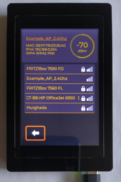
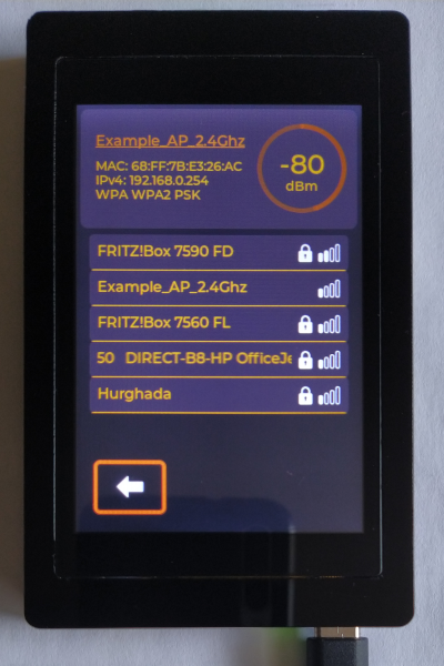
The RSSI value is shown by a number value that is placed inside an interactive Arc; the color of the Arc is set in according to signal strength (from green at -30dBm to red at -120dBm)
The pictures below shows some examples of different access points:
Set/run alarm
To set an alarm user should click the clock label on the main screen. A new screen shows summary information about all 4 alarms that are availiable to set. Every alarm can be activated and deactivated by simple switch on the right side, or modified by ckicking everywhere else on panel. By clicking on a panel, a new popup with detailed alarm values are created. User can set the time, text to be displayed when alarm plays, and days when alarm will be repeated. All the informations together with status od activation will be then stored in SPIFFS, so the alarm will stay active even after the OTC will restart.
To run an alarm, the clock_task check every minute if any of them should be played. If yes, it creates new popup on the main screen ans starts buzzer to play alarm_sound. The alarm can be turned off by press and hold the alarm panel for a few seconds.
Besides the components mentioned above, the OTC project was developed with use:


