MPI_Shift_Coils
The shift coils are a set of electromagnets that function to modulate the location of the FFL. This page covers the design process of these coils as well as the simulations which were used to come to that design. This page also describes some of the manufacturing concerns regarding the coils and associated components.
As the name implies, the function of the shift coils is to modulate the position of the FFL and form projections. To form projections the field produced by the shift coils must move the FFL by +/- FOV/2 to reach each edge of the field of view and include all of the particle information in the reconstruction. The frequency of the shift coils is directly coupled to imaging speed. For example, if you want to image at one image per five seconds, and have 27 projections in an image, you must shift at: 27 projections/image * 1 image/5 seconds = 5.4 projections per second With two projections per period, this means the shift frequency is 2.7 Hz
We opted for a "racetrack" style design with the new set of shift coils largely for the sake of manufacturability. The other concerns when designing the coils included field efficiency (how strong of a field can be produced per amp of current), amplifier matching, and thermal practicality. Field homogeneity, although certainly a consideration, is less important because slight inhomogeneities can be simply included in the reconstruction model. For those doing X-Space recon, this may be a bigger concern as field inhomogeneity may result in image distortion.
To maximize manufacturability as well as design flexibility we choose a design that is based on individual layers that are soldered together to form the full electromagnet.
Each coil consists of 10 layers of 20 turns each for a total of 200 turns and for these coils we are using 10 AWG solid core copper magnet wire. The layers are assembled in two full sets of four layers, and one half-set on the inner surface.Note the cross-section image below shows an extra heat-sink and turns.
 Note the implemented system has only 10 layers, so the bottom heat sink and bottom two layers are not there
In the previous desing, the system's duty cycle was limited by the shift coil heating. Given this, with the new coil design, we sought to maximize the heat dissipation by integrating heat sinks within the coils. We also have a thermally conductive Silicon Carbine compound between all layers to aide in the heat dissipation. We chose to use Rescor Castable Ceramics (Cat. No. 770, McMaster No. 8498K13, K=4.3W/(mK)) for its relatively high thermal conductivity and electrical insulation properties. Yet this SiC compound resembles a coarse paste/cement and is quite to spread with less than 1 mm thickness, therefore, we included 1.5mm of this compound in the model to be safe. Another possible option is to use an electrically insulating potting epoxy (e.g. McMaster Part No. 7563A26, K=1.8W/(mK)) doped with aluminum oxide or another thermally conductive, electrically resistive powder to increase the thermal conductivity. For example, when doped with 30% by volume of aluminum oxide, the effective thermal conductivity becomes ~3.3 W/(m*K), an 80% improvement (See the page on thermal conductivity of a matrix for details)
The heat sinks consist of a thin aluminum plate that sits between electromagnet layers and a thicker section containing a semi-circular groove that a copper tube is press-fit (and epoxied) into. The thin section enables sufficient heat transfer while not creating unnecessary spacing between the windings and the center of the bore. On the top (surface farthest from the bore)a heat sink spans the surface and consists of three press-fit copper tubes. Both the internal heat sinks and the top heat sink cover only 1/4 of the shift coil's surface; this is because if they encompassed the full shift coil geometry, substantial eddy currents would flow through all these heat sinks and reduce the efficiency, especially at higher temporal resolutions.
The following simulations were done in FEMM 4.2, a 2D electromagnetic and thermal simulation software package. It is free to use, relatively simple, and has reference tutorials. The files we used for these simulations are included with this GitHub page (.FEM files for magnetics, and .FEH for thermal).
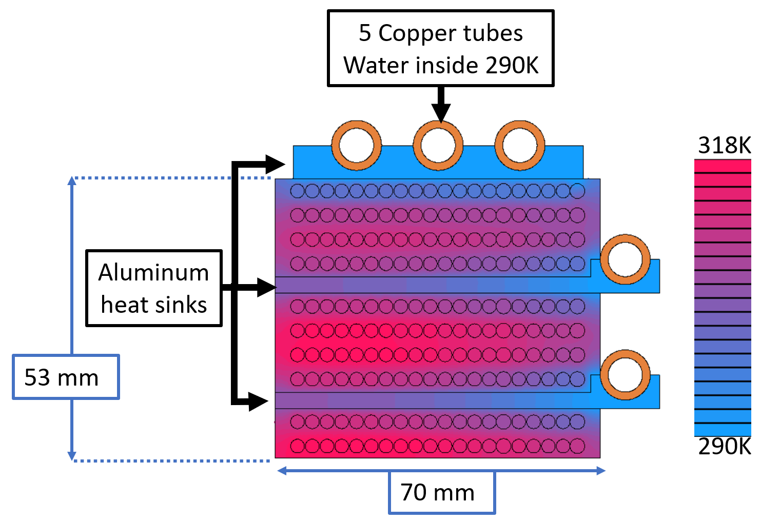

For the thermal simulations, we assumed isolated boundaries on all external faces besides those with water coolant. On the water coolant faces, we assumed a fixed temperature (290 K, although variation in this will only cause a scalar temperature shift for the whole coils).
To construct the magnets we used the winding jig that is also included on the OS-MPI page. Each planar layer was individually wound and then set in place with epoxy and soldered to the adjacent coil.