GUI for probing modbus TCP data, it also lets you attempt to write to coils and registers.
It's fairly basic and treats everything as integers, whereas some Modbus data needs treating as hex or other values, I intend to add some more format conversion capabilities at some point, but best laid plans and all that. If you're doing some analysis and suspect you need a different format, e.g. looking for character values, one option is to run wireshark to capture the data transfer, then use TCP->Follow Stream which will dump the contents into a window and allow you to decode to various formats.
Makes use of pyModbusTCP for all the hard work: https://github.com/sourceperl/pyModbusTCP
GUI components use the dearpygui framework: https://github.com/hoffstadt/DearPyGui
Requires Python 3.x with pyModbusTCP and dearpygui to be installed with:
sudo pip install dearpygui pyModbusTCP
Download the files pyModbusScanner-v0.x.py and SourceSans3-Regular.otf into the same directory, then run with:
python pyModbusScanner.py
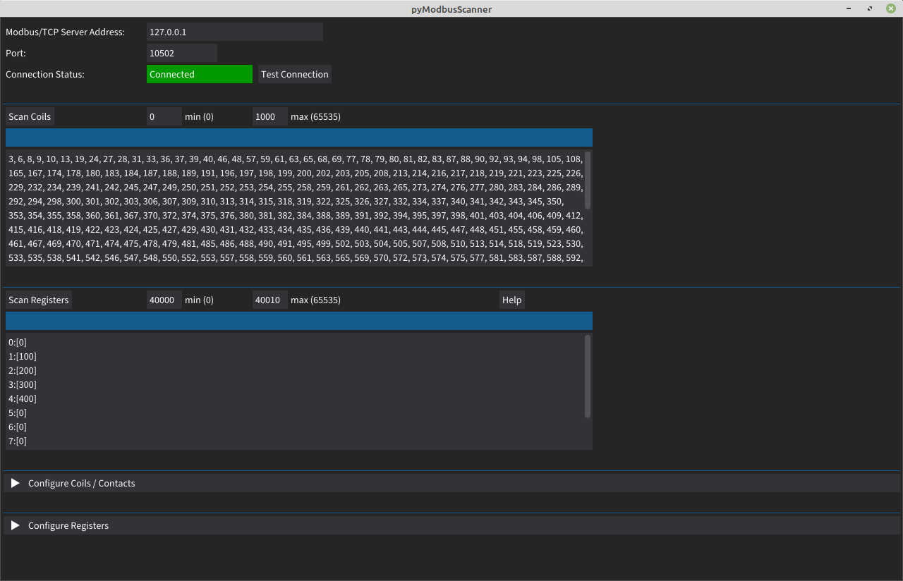
Fire it up, enter IP/port for modbus service, click "test connection" and verify that the status indicator goes green and says "Connected". Then enter max/min values for either coils, registers or input registers and hit the relevant "scan" button, results should appear in the box beneath.
Debug info gets dumped into the console so if it goes wrong then there may be some hints in the terminal you launched it from.
License is Beerware
Addresses can be anything from 1-65535, there is a modbus spec that defines recognised ranges but devices may not follow the spec, so for enumeration it may be sensible to scan everything. The official address ranges are:
- 1-9999 - discrete output coils R/W - binary
- 10001 - 19999 - discrete input contacts R/O - binary
- 30001 - 39999 - analog input registers - R/O - 16 bit int
- 40001 - 49999 - analog output holding registers - R/W - 16 bit int
It's sensible to start with small address ranges, especially if hitting a PLC with low resources.
Coil scanning will just show the address of any coils that are set to 1 rather than 0 as they're boolean values, scanning the registers will output the values held in those registers.
The values are fairly meaningless on their own as you need the context of what they represent and that isn't directly detailed in the protocol responses, these are just addresses and values, which this software treats as integers and that may not be the device intention. There's no information in the protocol responses that might indicate whether that value is a button status, pressure reading, kitkats remaining in stock, number of games of tictactoe that have been won, a text message to be printed on a billboard or any other possible value.
Registers are 16 bit, but some implementations may use 32 bit values by joining two 16 bit registers together. This software will just show two separate 16 bit values.
Spec is here: https://modbus.org/docs/Modbus_Messaging_Implementation_Guide_V1_0b.pdf
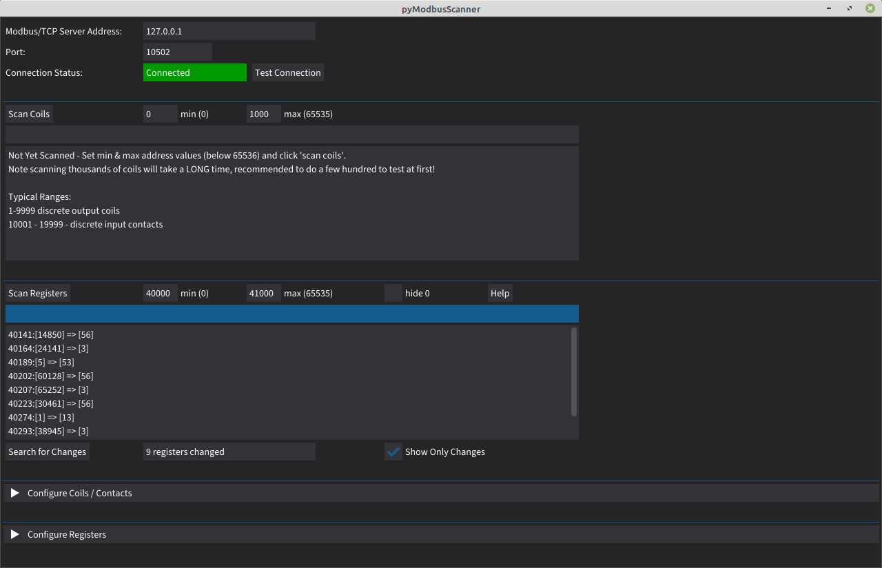
A feature added in 0.6 is ability to look for values that are changing. Run a register scan as normal, wait a while and then hit the "search for changes" button. If any values have changed then it'll tell you how many and you can hit "show only changes" to just display values that changed since the original scan was run.
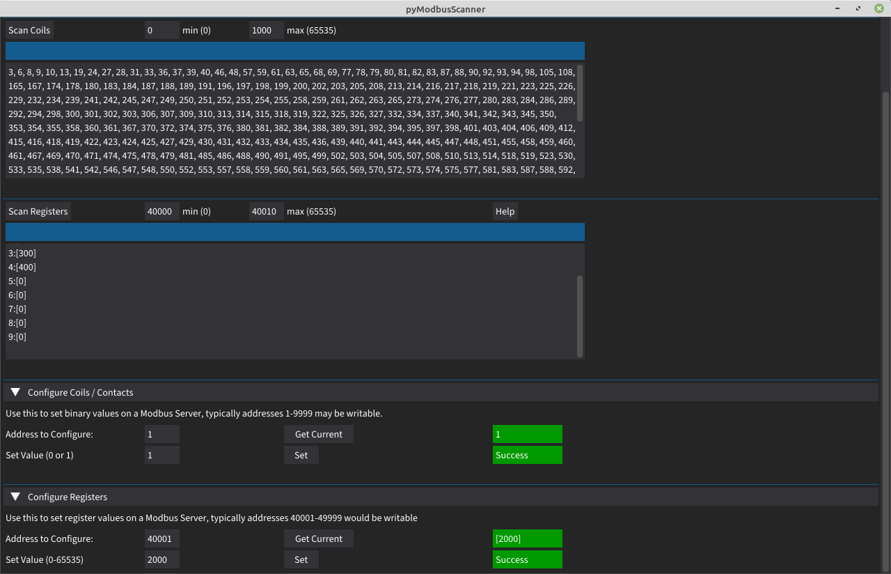
The process for writing values with this client is:
- Pick the address of the value you want to write, in the Modbus spec the R/W coils are 1-9999 and R/W registers are 40001-49999. Other values may be writable.
- Click "Get Current" to load the value in that coil/register currently on the server. Note if it's a value that changes over time, e.g. a voltage, then this won't work very well.
- Enter the new value in the "set value" box and click "set"
- If we didn't get any error responses then the status will show green with text "success".
- The client will then re-fetch that address from the server and re-populate the value box (next to the "get current" button). This should match up with the value you tried to set, if it doesn't then either the server has not accepted the updated value and responded like it has, or something else has changed it in the background.
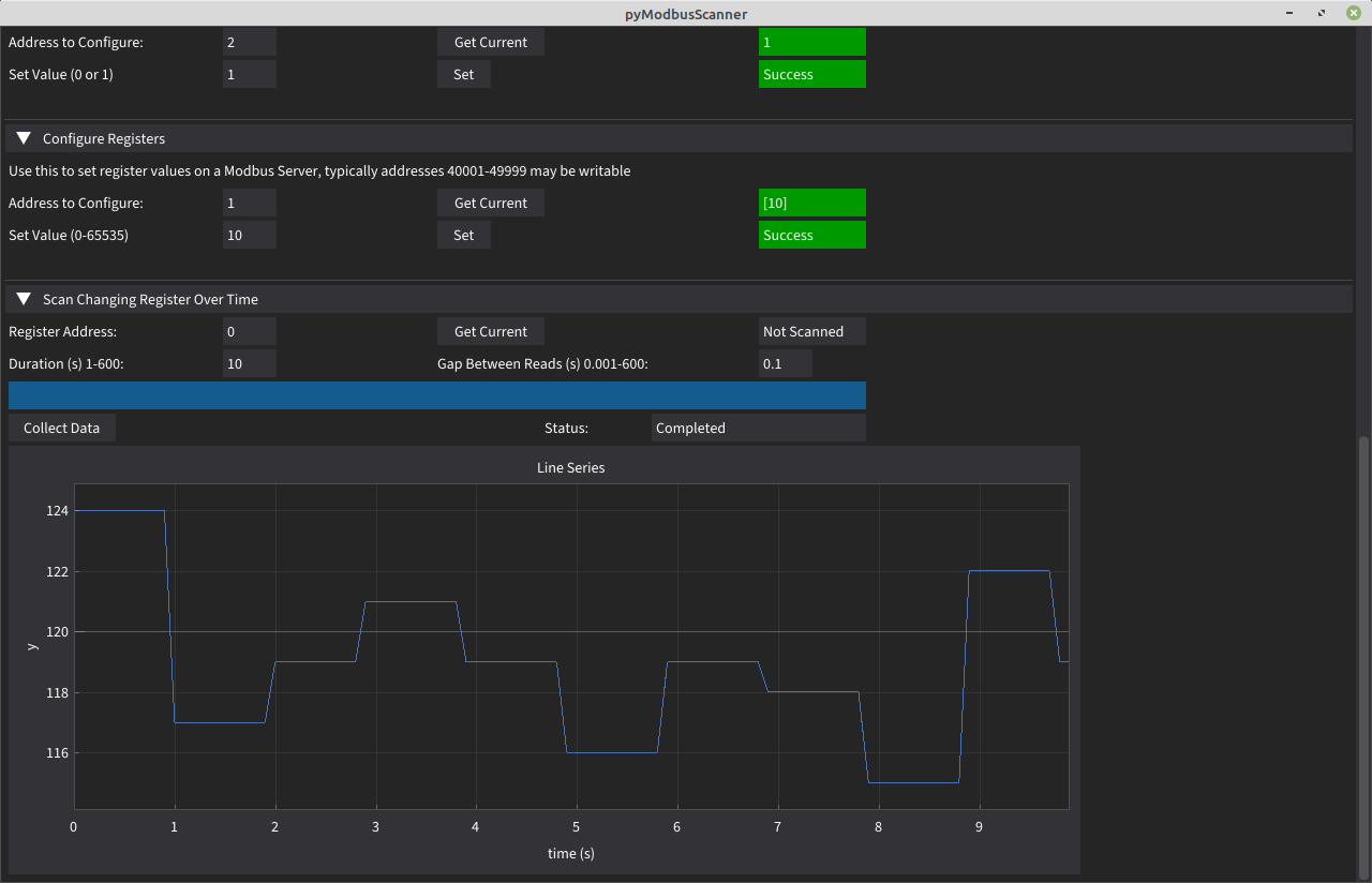
This function plots a changing value onto a graph, enter the register address to use as a data source, optionally click "get current" to double check it's readable and correct, set the duration as how long you want to collect data for and the gap to how long to leave between fetching data. Then hit "collect data" and if all is well it'll start rendering onto the graph as shown on screenshot below:

One option is to run the Modbus Server GUI that I'm working on: https://github.com/unixhead/pyModbusServerGUI
Another is to use the excellent Control Things Linux from here: https://www.controlthings.io/ Load up ModbusPal, hit "load" and open the included VoltageRegulator.xmpp (should be in /home/control/samples/Simulators/ModbusPal), click Run and that'll give you a Modbus Service to poke at.


